After acquiring all of the necessary components for the closed loop iSAVE system, assembly of the system follows a set of simple steps outlined below:
Assemble the inspiratory limb for each patient.
Assemble the exspiratory limb for each patient.
Combine one inspiratory limb with one expiratory limb for each patient.
Link the two inspiratory limbs together and attach to the outlet of the ventilator.
Attach each expiratory limb to inlets on the ventilator.
The following tutorials provide a visual guide for assembling the closed loop iSAVE system, as shown below.
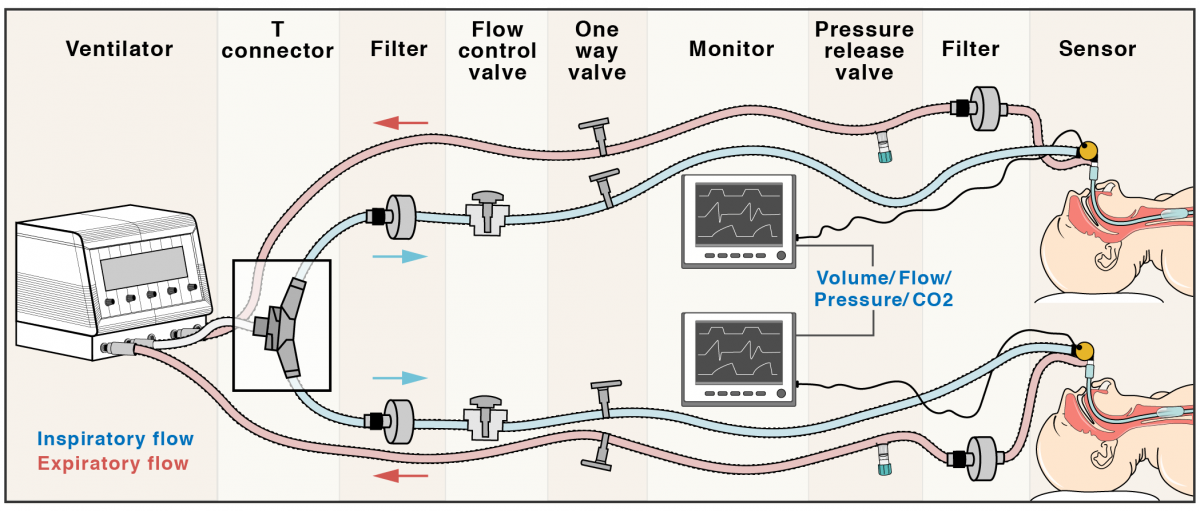
A complete, closed loop, iSAVE ventilatory device.
Visual Tutorial:
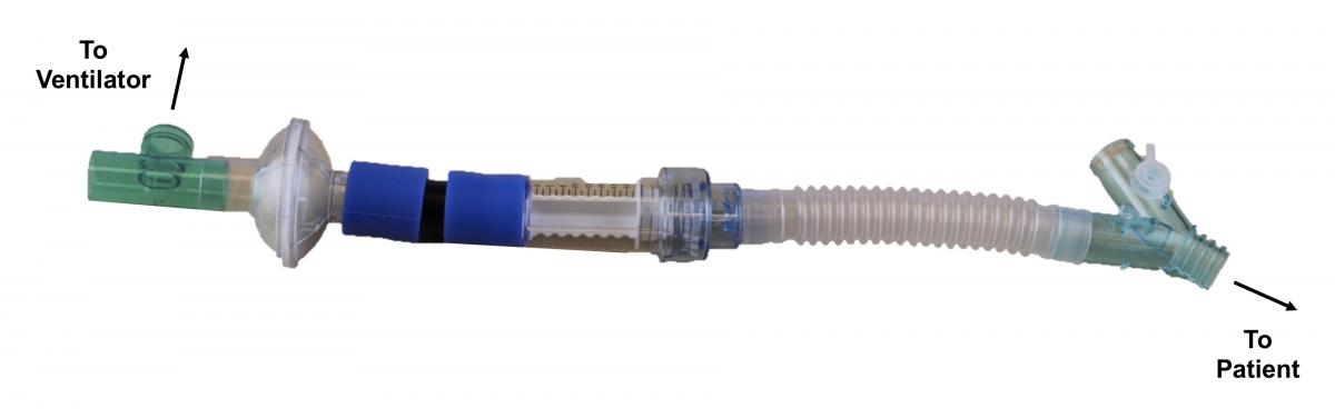
Inspiratory Limb Assembly
Begin with a T connector, on the end of the inspiratory limb closest to the ventilator.
Attach a filter to the distal end of the T connector.
Attach adapters to either end of a ball valve and then attach to the free end of the filter.
Attach the flow inlet end of a one-way valve, with PEP threshold, to the distal adapter.
Connect one branch of the Y connector, separated by tubing, to the free end of the one-way valve.
Completed Inspiratory Limb
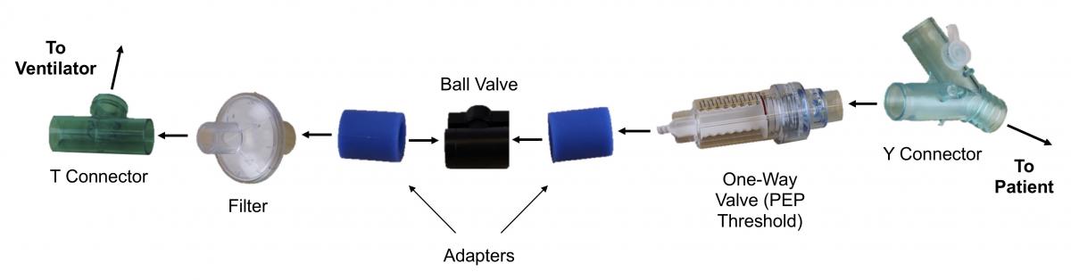
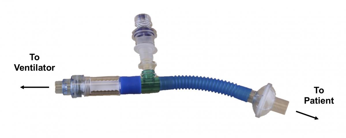
Expiratory Limb Assembly
Begin with a one-way valve, with PEP threshold, on the end of the expiratory limb closest to the ventilator.
Attach an adapter to the flow inlet end of the one-way valve.
Attach a pressure release (PEEP) valve to the perpendicular end of a T connector and attach one of the parallel ends to the distal side of the adapter.
Connect a filter to one end of a piece of tubing and then to the free end of the T connector.
Completed Expiratory Limb
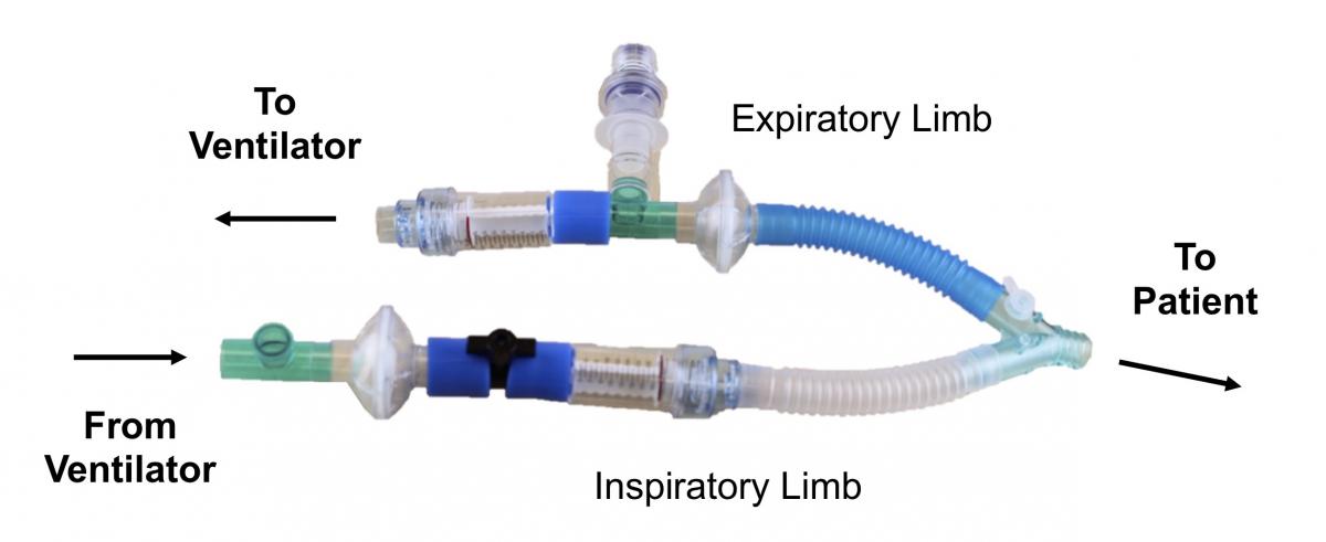
Completed Patient System
Connect the end of the expiratory limb tubing to the open branch of the Y connector on the inspiratory limb.
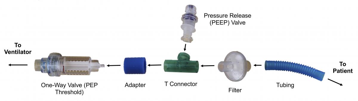
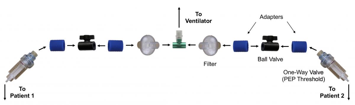
Inspiratory Limb Connector Assembly
Begin with a T connector that is able to attach to the ventilatory outlet on its perpendicular side and attach a filter to each end of the connector.
Attach an adapter to both ends of two ball valves, then attach one side of the adapter and ball valve complex to the open end of each filter.
Connect the inlet side of a one-way valve, with PEP threshold, to the distal end of each adapter.
Attach the inspiratory limb of each completed patient system to the outlet side of the one-way valves using tubing.
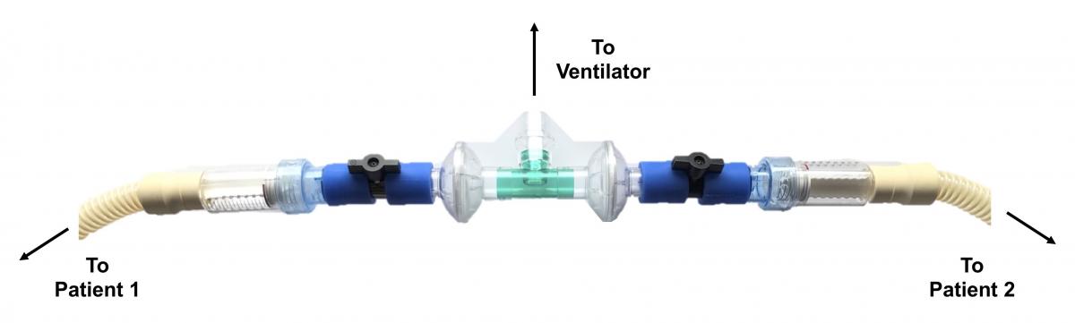
Completed Inspiratory Limb Connector
Set Up Procedure:
Initially, the respiratory rate, PEEP, FiO2, inspiration:expiration time, and the sum of the VT for both patients is set on the ventilator.
Flow control valves are titrated to provide the desired volume to each patient.
The exhaled volume and minute ventilation alarms on the ventilator are set based on the sum of the exhaled tidal volumes from both patients. Note: This alarm will enable the ventilator to notify clinicians in the case of any sudden changes in the volume delivered to each patient (e.g., shunt, occlusion or, disconnection of the endotracheal tube).
PEEP valves in each patient’s circuit should also be set to the maximum pressure allowable for that patient.
For Ventilators Using Closed-Loop Flow Control (such as Hamilton G5):
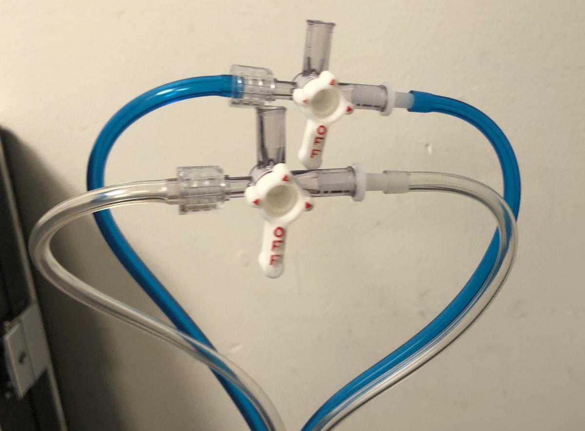
Connect flow sensors to Y-piece in their normal configuration to both patients
Using a standard stopcock, connect the blue tubes from either patient's flow sensor to either side of the stopcock. Repeat this for the clear tubes using another stopcock.
Attach the stopcock housing the blue tubes to the blue connector port on the ventilator.
Attach the stopcock housing the clear tubes to the silver connector port on the ventilator.
Step 2
Step 4
Recommendations for grouping patients based on ventilation needs are found here.
 Step 2
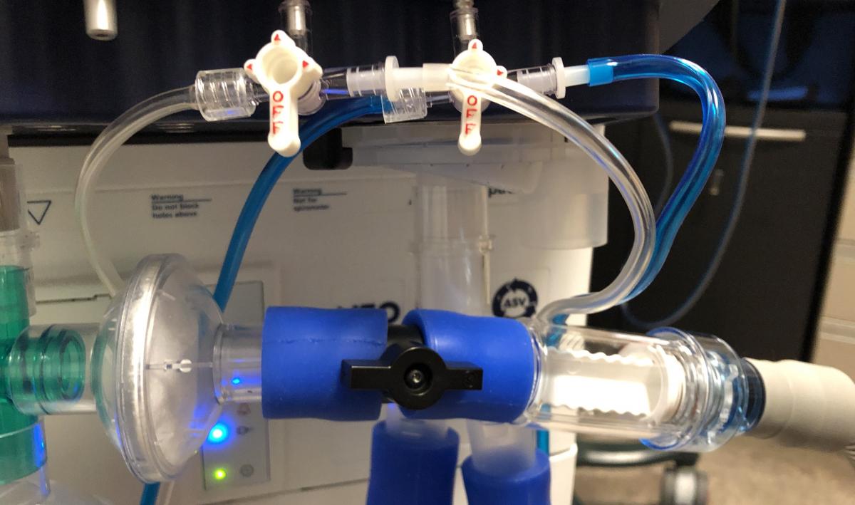 Step 4